
Double-Flanged Spacer Piece
Two flanges on a controlled pipe length bridge known mating faces. Therefore, face-to-face dimension, parallelism and bolt-hole orientation are critical.
A flanged spool piece is one identified piping section with at least one flange and a drawing-defined opposite end. The piece may connect two flanged interfaces, bridge a known gap, adapt a line size, connect equipment or replace a removed component. Therefore, its geometry comes from the piping design and field interfaces rather than a universal catalogue dimension.
A simple unit may contain a straight pipe length and two flanges. However, another piece may include an elbow, reducer, branch, coupling, welded attachment or prepared field-weld end. The drawing should identify every component and establish the controlling dimensions.
This page focuses on a shorter individual, connecting or replacement component. For complete flanged assemblies with multiple fittings and branches, visit our flanged pipe spool page. For material-neutral single-piece information, review pipe spool piece.
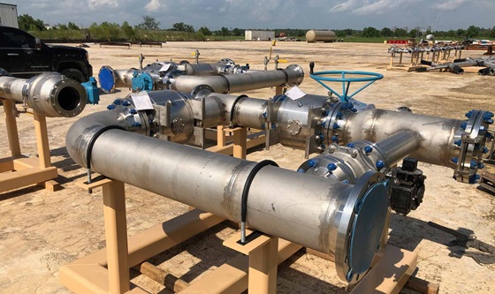
The installation purpose determines the arrangement. For example, a double-flanged spacer has different dimensional priorities from a flanged-to-weld-end closure piece. Common configurations include:
Two flanges on a controlled pipe length bridge known mating faces. Therefore, face-to-face dimension, parallelism and bolt-hole orientation are critical.
One flange connects a bolted interface, while the opposite end provides an approved field-weld preparation and closure allowance.
Similarly, a concentric or eccentric reducer connects different line sizes while maintaining the specified orientation and drainage arrangement.
An elbow and pipe extension can change direction between a flanged interface and another connection without defining a complete complex spool.
In addition, a controlled component can connect a valve, pump, vessel, exchanger, meter or packaged skid to the adjoining pipework.
Finally, a detachable section can support maintenance access, equipment removal, temporary substitution or replacement of damaged piping.
See removable spool piece for maintenance-led geometry and elbow spool for direction-changing assemblies.
The word flange does not provide enough information for manufacturing. Instead, the RFQ should state the complete designation for each end. The project must also confirm the governing standard and edition. For reference, the official ASME B16.5 flange standard covers specified ratings, materials, dimensions, tolerances, marking and testing within its stated size range. Meanwhile, ASME B16.47 addresses defined large-diameter steel flange applications.
| Designation item | Examples or options | Why it must be stated |
|---|---|---|
| Standard and edition | ASME B16.5, ASME B16.47 or another project-approved standard | Controls applicable dimensions, ratings, tolerances, materials and marking |
| Nominal size | NPS or DN designation for every flanged end | Establishes bore and mating dimensions within the selected standard |
| Pressure class or rating | Class 150, 300, 600 or another specified designation | Must match the approved design conditions, material group and mating system |
| Flange type | Weld neck, slip-on, socket-weld, threaded, lap-joint or another approved type | Changes the connection geometry, bore, welding and inspection requirements |
| Facing | Raised face, flat face, ring-type joint or project-specific facing | Defines the gasket interface and affects the controlled face-to-face dimension |
| Material | Approved forging, casting or plate specification and grade where permitted | Supports pressure-temperature suitability, weld compatibility and traceability |
| Bore and schedule | Standard bore, schedule bore or project-defined internal transition | Prevents mismatch with the connected pipe wall and flow path |
| Bolt-hole orientation | Straddle centerline, clocking angle or drawing-defined orientation | Controls installation fit where the mating flange position is fixed |
Selection note: A flange class alone does not establish suitability. The owner or appointed piping engineer must approve the standard, material, facing, rating and joint arrangement for the actual fluid, pressure, temperature and mating equipment.
Dimensional control starts before welding because heat and fit-up forces can move the assembly. First, the drawing should define datums and tolerances. Next, fabrication checks should verify flange location and orientation during fit-up. Finally, the release inspection should record the critical interfaces in the agreed format.
| Check | What it controls | Buyer input |
|---|---|---|
| Face-to-face length | Distance between gasket-contact faces on a double-flanged piece | Nominal dimension, tolerance, gasket basis and measurement temperature if relevant |
| Center-to-face dimension | Location of a flange relative to an elbow, branch or established centerline | Drawing datum and tolerance |
| Flange parallelism | Relationship between two mating faces on the same piece | Acceptance limit and measurement method |
| Face squareness | Flange-face orientation relative to the pipe axis | Specified angular or linear tolerance |
| Bolt-hole clocking | Rotational position of holes around the pipe centerline | Straddle requirement, top reference or stated angle |
| Bore alignment | Internal transition between pipe, weld neck, reducer and adjoining components | Permitted mismatch and taper requirements |
| Field interface | Fit between the new piece and fixed site connections | Verified survey, stable datums and installation allowance |
Our pipe spool drawing page explains how dimensions, weld references, component callouts and revisions guide production.
A controlled workflow connects the approved design to the finished component. Although the exact route depends on material and service, the following stages help preserve identity, flange geometry and weld quality.
First, the team checks the drawing revision, flange designations, materials, welds, dimensions and inspection points.
Next, identification and certificate review connect the pipe and flanges to the approved specifications.
Controlled cutting, beveling and cleaning establish the required length, joint preparation and fit-up surfaces.
Meanwhile, fixtures and in-process checks hold the face location, bore alignment and bolt-hole orientation.
Qualified personnel follow the applicable WPS, consumable, parameter, preheat, interpass and purge requirements.
Finally, visual, dimensional and specified NDT or testing records support release against the agreed criteria.
For wider manufacturing activities, review fabricated pipe spools and pipe spool services.
The approved ITP or QAP should identify every required inspection stage. Consequently, the final record package can connect the component to its materials, welding, dimensions, examinations, surface condition and release status.
First, certificates, heat numbers and PMI when specified can verify the required pipe and flange materials.
Next, checks can cover joint preparation, root gap, alignment, flange position and component orientation.
In addition, visual examination and specified PT, MT, RT or UT can assess welds against project criteria.
Reports may record face-to-face length, parallelism, squareness, flange clocking and other critical interfaces.
Likewise, the scope may include pressure testing, hardness, coating checks, passivation records or cleanliness verification.
Finally, a document index can organize drawings, certificates, weld maps, inspection reports and release notes.
See Quality Control and Testing for the broader pipe-spool inspection workflow.
A replacement component must match the actual field interfaces rather than an old nominal description alone. Therefore, the project should verify both mating faces, current site geometry, available installation clearance and the reason for replacement before releasing the new drawing.
For example, corrosion, settlement, vibration, previous modification or flange misalignment may have changed the real dimensions. In that case, approved field measurements or a verified scan may need to supersede the original drawing. Reproducing an outdated geometry can repeat the existing fit-up problem.
Engineering responsibility: The owner or appointed engineer should approve the replacement design, materials, dimensions, loads and acceptance criteria. Mesta Inc. can then review fabrication against that controlled technical basis.
To begin with, send the current approved drawing and state whether the requirement covers a new, replacement or removable piece. Also include:
Additionally, identify all fixed equipment interfaces and field measurements so the technical review can address fit-up risk before production.
A flanged spool piece is one identified piping section with at least one flange and a drawing-defined opposite end. It can connect pipework, equipment or a replacement location.
This page focuses on a shorter individual connector, spacer or replacement component. In contrast, a flanged pipe spool may describe a complete and more complex assembly with several fittings or branches.
Yes. For example, a double-flanged spool piece can bridge two known mating faces when the drawing defines its face-to-face length, flange details and bolt-hole orientation.
Provide the standard and edition, nominal size, pressure class or rating, flange type, facing, material, bore and bolt-hole orientation for every flanged end.
Bolt-hole clocking controls rotational alignment with a fixed mating flange. Therefore, the drawing should show the centerline or angular reference used for inspection.
A replacement enquiry can be reviewed when it includes an approved technical basis, verified field dimensions, exact flange and material details, inspection requirements and delivery needs.
Finally, the agreed dossier can include drawings, material certificates, weld maps, welding records, NDT reports, dimensional reports, test records, surface-treatment reports and release documents.
Send Mesta Inc. the approved drawing, exact materials, complete flange designations, critical dimensions, inspection requirements, surface specification and delivery date. Our team will review the manufacturing scope and identify any technical clarification needed for quotation.