
45-Degree Elbow Spool
A 45-degree elbow creates a gradual directional change. In addition, straight tangent lengths and end connections can complete the assembly.
Mesta Inc. manufactures each custom elbow spool for industrial piping systems. We control the elbow angle, radius, end connections, centre-to-end dimensions and assembly orientation so each spool follows the approved piping layout.
An elbow spool combines one or more pipe elbows with straight pipe sections and specified end connections. Depending on the layout, the assembly may also include flanges, reducers, branches, vents, drains or supports. Therefore, it creates a controlled change of direction within a larger piping system.
Mesta Inc. fabricates each pipe elbow spool from an approved isometric or pipe spool drawing. First, our team checks the angle, elbow radius, tangent lengths and end details. Then, fabricators control the plane, roll angle and orientation of every component during fit-up.
As a result, site teams receive an identified assembly that follows the planned geometry. Buyers can specify carbon steel, stainless steel, alloy steel or selected special alloys, along with welding, examination, testing, surface treatment and documentation requirements. For the broader manufacturing scope, review our custom fabricated pipe spools.
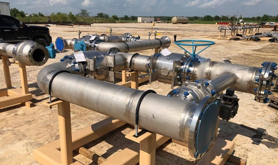
Our team reviews every enquiry against the piping class, approved drawing and inspection plan. Consequently, the quotation confirms final dimensions, materials, end connections and acceptance criteria. The project may reference official ASME B16.9 fitting requirements and ASME B31.3 Process Piping when those standards form part of the approved design basis. The following table outlines common project options.
| Nominal size | 1/2 in. to 48 in., subject to material, elbow type, wall thickness, configuration and handling limits. |
|---|---|
| Pipe wall | Schedule 5 through XXS and project-defined wall thicknesses, subject to size and material availability. |
| Elbow angles | 45-degree, 90-degree, 180-degree return and drawing-specific directional assemblies where available. |
| Radius options | Long radius, short radius and project-specified bends according to the approved piping class. |
| Materials | Carbon steel, stainless steel, alloy steel, Inconel, Monel, Hastelloy and other project-approved materials. |
| End connections | Butt-weld bevels, flanges, plain ends, threaded or socket-weld connections where the specification permits. |
| Applicable standards | Project-specified editions of ASME B16.9, ASME B16.5/B16.47, ASME B31.3 or B31.1, ASME Section IX and relevant ASTM material standards, as applicable. |
| Inspection and testing | Visual and dimensional inspection, PMI, PT, MT, RT, UT, hydrostatic or pneumatic testing according to the approved inspection plan. |
| Documentation | Material certificates, weld map, welding records, NDT reports, dimensional reports, test records and release documents as agreed. |
Procurement note: “90-degree elbow spool” does not fully define an assembly. Also specify nominal size, wall thickness, radius, material, tangent lengths, end connections, spool plane, orientation and inspection scope.
The piping layout determines the angle, radius and number of elbows. For example, a simple single-elbow spool changes direction once, while a multi-plane assembly routes the line around equipment or structural constraints.
A 45-degree elbow creates a gradual directional change. In addition, straight tangent lengths and end connections can complete the assembly.
A 90-degree elbow redirects the line by a right angle. Therefore, centre-to-end dimensions and final orientation require careful control.
A long-radius elbow uses the radius that the applicable fitting standard and piping class define. Projects commonly select it for smoother routing.
A short-radius elbow supports compact layouts where the piping design permits it. However, the purchaser must confirm suitability for the service.
One or more flanges create bolted end connections. Thus, flange type, class, facing and bolt-hole orientation become part of the dimensional review.
Two or more elbows can create offsets, U-shaped sections or multi-plane routes. Consequently, drawings must define every angle, plane and tangent length.
Elbow-spool accuracy depends on more than overall length. First, the drawing establishes elbow centre points, tangent lengths and the relationship between each end. Next, fabricators set the spool plane and any required roll angle before tack welding.
Inspectors then compare the completed geometry with the approved drawing. In particular, they check centre-to-end dimensions, end-to-end dimensions, angular orientation, flange clocking and branch positions. These checks help the installation team avoid forced alignment and field rework.
A controlled workflow connects drawing geometry, material identity, weld records and final spool marking.
First, engineering personnel check drawing revisions, dimensions, angle, radius, ends, welding requirements and inspection points.
Next, the material team matches pipes, elbows, flanges and fittings with the bill of materials and maintains identification.
Then, technicians cut tangent lengths, prepare weld ends and clean joint areas according to the approved fabrication documents.
Fabricators set the elbow centre, spool plane, roll angle, flange orientation and end dimensions before tack welding.
Afterwards, welders follow the qualified procedure, while inspectors perform the specified visual and non-destructive examinations.
Finally, the team completes dimensional checks, testing, finishing, tagging, end protection and the agreed documentation package.
Quality planning starts before fabrication. First, our team confirms material, welding, examination and documentation requirements. Then, inspectors monitor fit-up and welding through the approved inspection plan. In addition, buyers can specify hold points and third-party inspection.
Material identification and certificates connect the pipes, elbows and other components to each marked spool.
Weld maps, procedure references, welder identification and examination results support the quality package.
Inspectors verify angle, centre-to-end length, tangent dimensions, plane, roll angle and end orientation.
Depending on the inspection plan, the team may perform PMI, PT, MT, RT, UT and pressure testing.
Review our complete approach to pipe spool quality control and testing.
Industrial projects use elbow spools to route piping around structures, connect equipment at different elevations and create planned offsets. For instance, common applications include:
Additionally, projects that need bolted end connections can review our flanged pipe spool page. Material-specific projects can also explore stainless steel pipe spools and steel pipe spools.
To begin with, send a complete enquiry package. This information helps our team review the geometry and manufacturing scope accurately:
An elbow spool combines one or more pipe elbows with straight pipe and specified end connections. A workshop fabricates the complete assembly to an approved drawing so it creates the required direction change at the project site.
Common configurations use 45-degree and 90-degree elbows. In addition, projects may use 180-degree returns or drawing-specific bends when the piping class and manufacturing scope permit them.
A long-radius elbow has a larger centreline radius than a short-radius elbow of the same nominal size. Therefore, each option creates different layout, space and flow characteristics. The piping designer must select the appropriate type.
The spool plane defines the geometric relationship between connected pipe runs. However, a rolled elbow places the outlet in another plane. Consequently, the drawing must clearly define the plane, roll angle and end orientation.
Yes. An elbow spool can include one or more flanges, along with reducers, branches, vents, drains or supports. When flanges form part of the assembly, specify their standard, type, class, facing and bolt-hole orientation.
Buyers may request visual and dimensional inspection, PMI, liquid penetrant, magnetic particle, radiographic or ultrasonic examination. Moreover, the project may require hydrostatic or pneumatic testing and third-party inspection.
Provide the approved drawing, size, schedule, material, elbow angle, radius, tangent lengths, ends, plane and roll angle. Furthermore, include welding, NDT, testing, coating, documentation and delivery requirements.
Send Mesta Inc. your approved drawings, material requirements, geometry, quantities, inspection scope and delivery schedule. Our team will review the enquiry and define the appropriate fabrication, testing, documentation and dispatch scope.