
P&ID
A piping and instrumentation diagram communicates process relationships, line identities, equipment, valves and instruments. However, it does not normally provide shop fabrication dimensions.
Mesta Inc. provides pipe spool drawing services that translate approved piping information into clear fabrication instructions. Each pipe spool drawing can define spool identity, dimensions, components, weld joints, orientation, material requirements and inspection notes for production.
A pipe spool drawing is a detailed shop document for one manageable section of a piping system. It converts approved design information into the dimensions, component details and production references that fitters, welders, inspectors and material-control teams need.
Typically, a parent piping isometric covers a complete line or a larger piping route. In contrast, the spool drawing isolates one fabrication unit and gives it a unique spool number. Therefore, the workshop can track material, fit-up, welding, inspection and release against a defined physical assembly.
Mesta Inc. supports project-specific drawing requirements as part of the spool workflow. Furthermore, our pipe spool assembly and fabricated pipe spool pages explain how approved drawings guide workshop production.
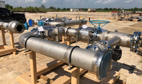
Project standards determine the exact pipe spool drawing format. However, a useful fabrication sheet should communicate the following information without forcing the workshop to infer critical details.
| Document identity | Project, unit, line number, parent isometric, spool number, sheet number, revision and issue status. |
|---|---|
| Piping geometry | Cut lengths, face-to-face and centre-to-face dimensions, offsets, elevations, angles, slopes and orientation references. |
| Components | Pipe, fittings, flanges, branches, valves, supports and attachments with item numbers and descriptions. |
| End conditions | Flanged, bevelled, plain, threaded or socket-weld ends, plus field-joint and tie-in identification. |
| Flange information | Type, class, facing, bore, orientation and any project-specific bolt-hole clocking. |
| Weld information | Shop and field weld symbols, joint numbers, weld type and references to project welding or examination requirements. |
| Material list | Itemized quantity, nominal size, schedule or wall thickness, material grade and component standard where required. |
| Quality notes | NDT extent, PWHT, PMI, pressure testing, dimensional checks or hold-point references when the project specifies them. |
| Finishing and marking | Coating, painting, pickling, passivation, insulation, tracing, spool marking and preservation notes where applicable. |
Drawing-control note: A spool sheet should identify its issue purpose clearly. The project team should never treat a preliminary, review-only or superseded revision as authorization for fabrication.
A pipe spool drawing, piping isometric, GA and P&ID each answer a different question. Therefore, one document cannot automatically replace another.
A piping and instrumentation diagram communicates process relationships, line identities, equipment, valves and instruments. However, it does not normally provide shop fabrication dimensions.
A GA drawing shows physical layout, equipment relationships and routing context. In addition, it may provide elevations and reference dimensions for coordination.
An isometric represents a three-dimensional piping route on a two-dimensional sheet. Typically, it covers more than one fabrication spool and identifies spool breaks or field joints.
A spool drawing details one fabrication unit. Consequently, it focuses on shop dimensions, item callouts, weld joints, material quantities and spool-specific identification.
The pipe spool drawing workflow maintains the connection between approved design information and workshop output through controlled review and revision steps.
First, the drawing team checks source-document revisions, piping classes, line lists, project conventions and client deliverables.
Next, the team defines practical spool limits around field joints, transport dimensions, lifting, access and erection sequence.
Then, detailers add dimensions, component callouts, weld numbers, end conditions, material data and required notes.
A checker compares geometry, dimensions, materials, orientation and references with the approved source information.
Afterwards, the responsible parties resolve comments and record the accepted revision according to the project procedure.
Finally, document control issues the approved drawing and distributes later revisions through a traceable change process.
Pipe spool drawing quality depends on disciplined checking rather than appearance alone. First, the checker confirms that the sheet matches the latest approved source documents. Next, the checker verifies that dimensions and item data describe a buildable, transportable spool. Applicable projects may reference ASME Y14.5 dimensioning and tolerancing and ASME B31.3 Process Piping alongside their approved drawing standards.
The agreed pipe spool drawing document index should define every required output. For example, a project may request individual spool sheets, a spool register, material summaries, weld maps and revision transmittals. In addition, the purchaser should specify file format, numbering rules, title-block requirements and review status codes.
Each sheet identifies one fabrication unit and provides its geometry, components, welds, ends and notes.
The register connects spool numbers with lines, drawings, revisions, quantities and production or delivery status.
Itemized bills of materials and agreed summaries support procurement, kitting and material control.
Transmittals, comment responses and revision histories help teams identify the current approved information.
A pipe spool drawing acts as a shared production reference. Material-control personnel use item numbers for kitting, while fitters use dimensions and orientation references during assembly. Likewise, welders and inspectors use joint numbers to connect physical welds with procedures and reports.
After fabrication, dimensional inspectors compare the completed spool with the approved sheet. Finally, spool numbers and orientation marks connect the released assembly to packing lists and the site erection sequence. Learn more about pipe spool quality control and testing and our pipe spool services.
To request pipe spool drawing services, provide the latest approved design basis and explain the required drawing output. Also include:
Responsibility note: The enquiry should define design ownership and approval authority. Drawing preparation does not replace piping design verification, stress analysis, code review, site survey or client approval unless the contracted scope explicitly includes those services.
A pipe spool drawing details one workshop-fabricated piping section. It normally identifies the spool, dimensions, components, weld joints, end conditions, material requirements and project notes.
Not always. A piping isometric often covers a complete line or several spools. In contrast, a spool drawing isolates one fabrication unit and provides spool-specific shop information.
The drawing should show the dimensions needed to fabricate and inspect the spool, such as cut lengths, centre-to-face dimensions, offsets, angles, elevations and overall or face-to-face dimensions. In addition, it should identify the measurement reference points clearly.
Shop and field weld labels define the fabrication boundary and planned site connections. Therefore, they help teams divide work, track weld records and coordinate installation.
A spool break divides a piping route into manageable fabrication and transport sections. The project team selects breaks by considering field joints, size, weight, lifting, access, coating, testing and erection sequence.
The drawing process needs approved geometry, dimensions, line and piping-class references, component details, weld requirements and spool boundaries. Furthermore, the team needs the latest revision and all relevant project specifications.
No, unless the project's document procedure explicitly gives it that status. Consequently, the title block and transmittal should clearly identify review, approval and fabrication-release status.
Send Mesta Inc. your approved source drawings, piping specifications, required deliverables, quantities and schedule. Our team will review the available information and clarify the drawing, checking, revision and fabrication-support scope.