
Weld Neck Flanged Spools
A tapered hub and butt-weld connection support stress transfer and bore continuity when the project specification requires this design.
Mesta Inc. manufactures custom flanged pipe spools for industrial piping systems. We control flange type, pressure class, facing, orientation and overall dimensions so each assembly supports efficient bolted installation at the project site.
A flanged pipe spool combines a pipe section with one or more welded flanges. Depending on the drawing, the assembly may also include elbows, tees, reducers, branch connections, supports or other specified components. Therefore, site teams can position and bolt the completed spool into a piping system instead of welding every connection in the field.
Mesta Inc. produces each custom flanged pipe spool from an approved isometric or pipe spool drawing. During production, our team controls flange alignment, bolt-hole orientation, face-to-face dimensions and fitting locations. As a result, the assembly matches the project layout and installation sequence.
In addition, buyers can define the material, pipe schedule, flange standard, pressure class, facing, surface finish, inspection scope and documentation package. For broader fabrication capabilities, review our fabricated pipe spools page.
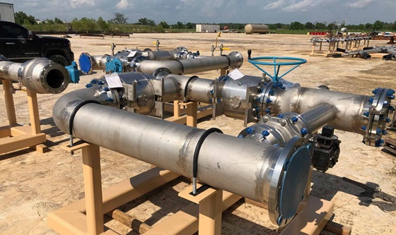
Our team reviews each enquiry against the piping class, approved drawing and project specification. Consequently, the quotation confirms the exact manufacturing range and inspection scope. The following table outlines common project options.
| Nominal size | 1/2 in. to 48 in., subject to material, flange standard, pressure class, wall thickness and configuration. |
|---|---|
| Pipe wall | Schedule 5 through XXS and project-defined wall thicknesses, subject to size and material availability. |
| Materials | Carbon steel, stainless steel, alloy steel, Inconel, Monel, Hastelloy and other project-approved materials. |
| Flange types | Weld neck, slip-on, socket-weld, lap-joint, threaded and blind flanges, where the piping class permits. |
| Pressure classes | ASME Classes 150, 300, 600, 900, 1500 and 2500 where the selected flange standard, size and material permit. |
| Facing options | Raised face, flat face and ring-type joint, with project-specified surface finish and protective covers. |
| Applicable standards | Project-specified editions of ASME B16.5, ASME B16.47, ASME B16.9, ASME B31.3 or B31.1, ASME Section IX and relevant ASTM material standards, as applicable. |
| Inspection and testing | Visual and dimensional inspection, PMI, PT, MT, RT, UT, hydrostatic or pneumatic testing according to the approved inspection plan. |
| Documentation | Material certificates, weld map, welding records, NDT reports, dimensional reports, test records and release documents as agreed. |
Important: A pressure class alone does not fully define a flange. Always specify the governing standard, nominal size, material, type, facing, bore, schedule or wall thickness, surface finish and any special drilling requirements.
The piping class and service conditions guide flange selection. For example, a project may choose a weld neck flange for demanding service or a slip-on flange for an approved general application. However, the buyer's specification always governs the final choice.
A tapered hub and butt-weld connection support stress transfer and bore continuity when the project specification requires this design.
The pipe enters the flange bore before welding. Therefore, fabricators must control insertion depth, weld size and final face alignment.
A backing flange works with a stub end. As a result, installers can rotate the flange during bolt-hole alignment where the design permits.
Blind flanges close a line end or provide future access. In addition, the drawing may include vents, drains or instrument connections.
Flanges at both ends create a complete bolt-in section. Precise face-to-face length, parallelism and bolt-hole orientation remain critical.
Elbows, tees and reducers can join one or more flanges. Thus, one shop-built unit can replace several field fit-up operations.
Correct flange geometry directly affects site fit-up. First, fabricators use the approved drawing to establish the spool centreline, face-to-face length and branch locations. Next, they control flange squareness, parallelism and rotational orientation during fit-up.
Inspectors then check critical dimensions before and after welding. In particular, they verify flange-face condition, bolt-hole clocking, overall length, branch angle and fitting orientation. These checks help prevent forced alignment, incorrect gasket loading and avoidable site rework.
A controlled sequence connects the approved drawing, materials, weld records and final spool identification.
First, the team checks drawing revisions, piping class, flange details, weld requirements, tolerances and inspection points.
Next, material-control personnel match pipe, fittings and flanges with the bill of materials and maintain identification.
Then, technicians cut pipe, prepare weld ends and clean joint areas according to the approved fabrication documents.
Fabricators set face-to-face dimensions, flange alignment, bolt-hole rotation and fitting positions before tack welding.
Afterwards, welders follow the qualified procedure, while inspectors complete the specified visual and non-destructive examinations.
Finally, the team completes dimensional checks, testing, surface treatment, tagging, face protection and dispatch documentation.
Quality planning starts with the enquiry review. First, our team identifies material-control, welding, examination and documentation requirements. Then, inspectors follow the approved inspection and test plan through fabrication. In addition, buyers can nominate hold points or third-party inspection when the purchase specification requires them.
Component identification and material certificates connect the pipe, fittings and flanges to the marked spool.
Weld maps, procedure references, welder identification and examination results support the quality record.
Inspectors compare flange position, face-to-face length, bolt-hole orientation and assembly geometry with the approved drawing.
Depending on the inspection plan, the scope may include PMI, PT, MT, RT, UT and pressure testing.
Learn more about our approach to pipe spool quality control and testing.
Industrial projects use flanged spools wherever bolted connections improve installation, equipment access or future maintenance. For instance, common applications include:
A flanged assembly may also support planned removal. Therefore, projects with frequent maintenance access should review our removable spool in piping page. For a directional assembly, see our elbow spool capability.
This page covers a complete flanged piping assembly, which may contain several pipe sections, fittings, branches or attachments. In contrast, a flanged spool piece usually describes a shorter individual section that connects two points or supports replacement and maintenance.
Consequently, use this page when you need made-to-drawing assembly fabrication. Visit the flanged spool piece page when your enquiry concerns a defined replacement or detachable component. This distinction gives each page a unique search purpose and prevents keyword cannibalization.
To begin with, send a complete enquiry package. The following information helps our team review your requirement accurately:
A flanged pipe spool combines a pipe section with one or more flanges and, when required, fittings or branches. A workshop fabricates the assembly to an approved drawing so site teams can install it through bolted flange connections.
A double flanged pipe spool has a flange at each end. Therefore, fabricators must control the face-to-face length, flange parallelism, bolt-hole orientation and specified facing so installers can connect both ends correctly.
Depending on the piping class, a spool may use weld neck, slip-on, socket-weld, lap-joint, threaded or blind flanges. However, service conditions, governing standards and the approved project specification determine the final type.
Specify the flange standard, nominal size, pressure class, material, type, facing, bore, pipe schedule, sealing-surface finish and any special drilling or orientation. In addition, provide the approved drawing and piping class.
Correct bolt-hole orientation helps the spool align with mating equipment and adjacent piping. Consequently, the drawing should define the required clocking or project convention, especially for elbows, branches and offset assemblies.
Buyers may request visual and dimensional inspection, PMI, liquid penetrant, magnetic particle, radiographic or ultrasonic examination. Moreover, the agreed scope may include hydrostatic or pneumatic testing and third-party inspection.
Yes. When the order includes them, Mesta Inc. can provide specified surface preparation, painting, coating, pickling, passivation and preservation. Furthermore, the document package can include material certificates, weld records, NDT reports, dimensional reports and test records.
Send Mesta Inc. your approved drawings, flange specifications, materials, quantities, inspection requirements and delivery schedule. Our team will review the enquiry and define the appropriate fabrication, testing, documentation and dispatch scope.