
Pipes and End Connections
Straight pipe sections can terminate in flanges, butt-weld bevels, plain ends, threaded ends or socket-weld connections where the specification permits.
Mesta Inc. provides pipe spool assembly services from approved drawings and project specifications. Each custom pipe spool assembly receives controlled component fit-up, welding, flange and branch orientation, dimensional inspection and spool identification before dispatch.
Pipe spool assembly brings specified pipes, fittings, flanges and attachments together into a transportable piping section. Depending on the drawing, one assembly may include elbows, tees, reducers, branches, couplings, vents, drains, supports, valves or instrument connections. Therefore, careful fit-up turns separate components into one controlled spool.
Mesta Inc. follows the approved isometric or pipe spool drawing throughout assembly. First, our team checks revision status, component identity and critical dimensions. Then, fabricators position each item, control orientation and prepare the joints for qualified welding.
As a result, the completed spool supports efficient inspection, transport and site installation. For the broader cutting and welding capability, review our fabricated pipe spools. For off-site project benefits, visit our prefabricated pipe spools page.
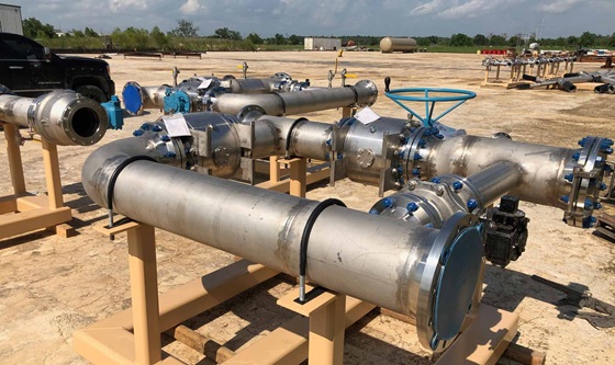
The piping class, bill of materials and approved drawing define each pipe spool assembly. For example, a simple spool may combine a straight pipe and two flanges, while a complex spool may contain several fittings, branches and attachments.
Straight pipe sections can terminate in flanges, butt-weld bevels, plain ends, threaded ends or socket-weld connections where the specification permits.
Elbows create horizontal, vertical or rolled direction changes. Consequently, the drawing must define angle, plane and orientation.
Tees, outlets and branch fittings create distribution points. In addition, fitters control branch location, angle and projection.
Concentric or eccentric reducers connect different sizes. Therefore, the assembly team checks reducer orientation and flat-side position.
Flange type, class, facing, bore and bolt-hole clocking follow the piping class and approved drawing.
When specified, assemblies can include supports, clips, vents, drains, couplings and instrument or valve interfaces.
For each pipe spool assembly, our team reviews the approved drawings, piping class and inspection plan. Consequently, the quotation confirms the final manufacturing range and project deliverables. When applicable, buyers can consult ASME B31.3 Process Piping and the broader ASME codes and standards resources alongside the approved project documents.
| Nominal size | 1/2 in. to 48 in., subject to material, wall thickness, geometry, component availability and handling limits. |
|---|---|
| Pipe wall | Schedule 5 through XXS and project-defined wall thicknesses, subject to size and material availability. |
| Materials | Carbon steel, stainless steel, alloy steel, Inconel, Monel, Hastelloy and other project-approved materials. |
| Assembly components | Pipes, elbows, tees, reducers, flanges, branches, couplings, vents, drains, supports and agreed inline items. |
| Welding processes | GTAW/TIG, SMAW, GMAW/MIG, FCAW and SAW according to the qualified procedure and production requirement. |
| Applicable requirements | Project-specified editions of ASME B31.3 or B31.1, ASME Section IX, relevant ASME component standards and ASTM material standards, as applicable. |
| Inspection and testing | Visual and dimensional inspection, PMI, PT, MT, RT, UT, hydrostatic or pneumatic testing according to the approved plan. |
| Finishing | Blasting, painting, coating, pickling, passivation or project-specified preservation. |
| Documentation | Material certificates, weld map, welding records, NDT reports, dimensional reports, test records and release documents as agreed. |
Project note: Transport envelope, lifting method, site access and erection sequence can limit spool size even when the workshop can fabricate a larger assembly. Define these constraints before final spool-break approval.
The pipe spool assembly process connects approved documents, component identity, weld status and final spool marking through a controlled workflow.
First, engineering personnel check drawing revisions, piping classes, bills of materials, weld details, tolerances and inspection points.
Next, the material team identifies and groups the required pipe, fittings, flanges and attachments for each spool number.
Then, technicians cut pipe, prepare ends and arrange components according to the drawing and planned weld sequence.
Fitters set root gaps, centreline relationships, flange orientation, branch position and overall geometry before tack welding.
Afterwards, welders follow the qualified procedure, while inspectors perform the specified visual and non-destructive examinations.
Finally, the team completes dimensional checks, testing, finishing, marking, end protection and the agreed document package.
Accurate pipe spool assembly fit-up establishes the final geometry. First, fitters locate components from drawing reference points rather than accumulated field measurements. Next, they control root gap, hi-lo alignment, branch projection, elbow plane, reducer orientation and flange clocking.
The assembly team also considers weld shrinkage and distortion. Therefore, the approved weld sequence, restraint method and intermediate dimensional checks matter on complex or heavy-wall spools. Inspectors then compare critical dimensions with the approved drawing before final release.
Some pipe spool assembly packages require a trial fit before dispatch. For example, a project may need to verify equipment interfaces, connecting-spool geometry, bolt-up alignment or a compact module. In that case, the approved inspection plan should identify the assembly extent and acceptance checks.
During the trial, the team joins designated spools or positions them against templates and reference points. Inspectors then record alignment, dimensions and interface conditions. Afterwards, workers separate the shipment sections, restore identification marks and protect flange faces or weld ends for transport.
Important: A successful shop trial does not replace site survey, foundation, equipment-nozzle or erection checks. The project must control every interface through the approved drawings and installation procedure.
Pipe spool assembly quality planning starts before component kitting. First, our team confirms material, welding, dimensional, examination and documentation requirements. Then, inspectors follow the approved inspection and test plan through fit-up and final release. In addition, buyers can nominate hold points or third-party inspection.
Material identification and certificates connect each pipe, fitting, flange and attachment to the marked spool.
Weld maps, procedure references, welder identification and examination results support the quality package.
Inspectors compare critical dimensions, orientation and interface points with the approved drawing.
Depending on the plan, the scope may include NDT, pressure testing, final inspection and release documentation.
Review our full approach to pipe spool quality control and testing.
Workshop pipe spool assembly moves fit-up, welding, inspection and identification into a controlled production environment before site installation.
First, workshop access helps fitters position, rotate and measure components more consistently than many field locations allow.
As a result, completed assemblies reduce loose-component handling, fit-up and production welding at the installation area.
Moreover, inspectors can review fit-up, welds, dimensions and documents before the spool leaves the workshop.
Finally, spool numbers, orientation marks and grouped packing help site teams receive and install assemblies in sequence.
To request pipe spool assembly services, send the latest approved project documents. Also include:
A pipe spool assembly combines pipe with specified fittings, flanges and attachments in a workshop. The approved drawing defines its dimensions, materials, weld joints, orientation and spool identification.
An assembly may include pipes, elbows, tees, reducers, flanges, branch fittings, couplings, vents, drains and supports. In addition, the agreed scope may include valves or instrument interfaces.
Fabrication describes the broader manufacturing work, including cutting, preparing and welding components. In contrast, assembly emphasizes positioning those components into the complete drawing-defined spool. In practice, both activities form part of one coordinated workflow.
Correct orientation helps the spool align with connected equipment and piping. Therefore, fitters and inspectors must control bolt-hole clocking, flange-face position, branch angle and projection.
A purchaser may request trial assembly for complex interfaces, connecting spools, equipment tie-ins or compact modules. However, the approved inspection plan must define the trial extent, reference points and acceptance criteria.
Each spool can carry a unique number that corresponds to its drawing and line reference. Moreover, orientation marks, colour coding, packing lists and delivery groups can support site receiving and erection.
Provide approved drawings, bills of materials, piping classes, quantities, materials, dimensions and weld requirements. Furthermore, include inspection, testing, coating, documentation, transport and delivery-sequence requirements.
Send Mesta Inc. your approved drawings, bills of materials, quantities, inspection scope and delivery schedule. Our team will review the enquiry and define the appropriate kitting, assembly, welding, testing, documentation and dispatch scope.