
Pump and Compressor Access
Consequently, a detachable suction or discharge section may provide clearance for servicing or removing equipment components.
Removable spool in piping design supports planned maintenance access, equipment removal and controlled physical separation. This guide explains equipment interfaces, isolation arrangements, flange compatibility, removal clearance and the information engineers should resolve before fabrication.
A removable spool in piping is a planned section that maintenance personnel can detach after they make the system safe under an approved site procedure. Typically, it has flanged connections at both ends. Therefore, teams can create access without cutting permanent pipe or dismantling a much larger piping run.
For example, the spool may sit near a pump, compressor, valve, meter, strainer, heat exchanger or another item that needs inspection or removal. In addition, some process designs use spool removal as one element of a positive-isolation arrangement. The piping designer must define that function on the P&ID and in the operating philosophy.
For commercial specifications and quotation requirements, visit our custom removable spool piece page. For a broad individual-spool product, see our pipe spool piece page. Additionally, our flanged pipe spool guide explains common flange configurations.
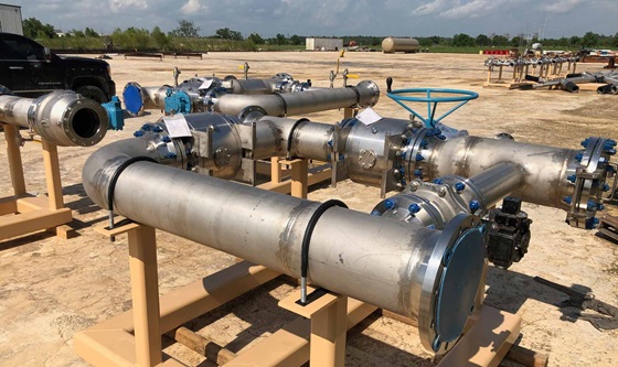
Designers use a removable spool in piping where recurring access or physical separation justifies additional flanged joints. For example, common applications include:
Consequently, a detachable suction or discharge section may provide clearance for servicing or removing equipment components.
Likewise, a removable connection can preserve access for channel covers, headers or tube-bundle handling when the layout requires it.
Moreover, a planned spool can create dismantling space for inline equipment without cutting adjoining pipe.
For instance, meter runs or instrument assemblies may use a removable flanged section for inspection, calibration or replacement access.
In particular, selected clean or hygienic systems may use a removable section to inspect internal condition at a representative location.
Furthermore, some approved isolation philosophies use spool removal and correctly rated blinds to create a visible physical break.
The piping arrangement determines whether a removable spool in piping provides useful access. Therefore, designers should define its function before selecting spool dimensions or flange locations.
| Intended function | Role of the spool | Engineering question |
|---|---|---|
| Equipment withdrawal | Creates space to remove a pump casing, valve, strainer or another maintainable item. | Does the spool length provide the full maintenance envelope? |
| Heat-exchanger access | Keeps piping clear of channel, header or tube-bundle removal paths. | Can maintenance proceed without disturbing unrelated piping? |
| Inspection opening | Provides access to inspect a selected internal piping location. | Is this location representative, accessible and safe to open? |
| Meter or instrument access | Allows planned removal or calibration of a connected assembly. | How will fixed interfaces, straight-run needs and alignment remain controlled? |
| Physical line break | Creates visible separation when an approved isolation philosophy specifies spool removal and blinding. | Which valves, drains, vents, blinds and verification steps does the site procedure require? |
| Future modification | Preserves a defined bolted interface for an approved system change. | How will the project control pressure rating, dead legs and unauthorized connection? |
Product information: Buyers who need available sizes, materials, welding processes and RFQ details should use the dedicated removable spool piece manufacturer page.
A removable spool in piping needs more than two flanges and a pipe length. Instead, the final design must coordinate process duty, piping flexibility, equipment access, joint integrity and safe handling. In addition, the governing project may reference ASME B31.3 Process Piping or another approved construction code.
| Design item | Why it matters | Information to provide |
|---|---|---|
| Face-to-face dimension | Controls fit between fixed piping or equipment interfaces. | Approved overall length, gasket allowance, tolerance and field-fit strategy |
| Flange compatibility | Prevents mismatched ratings, facings, bores and bolt patterns. | Standard, type, pressure class, facing, material, bore and bolt-hole orientation |
| Service conditions | Influence material, wall, gasket, bolting and examination requirements. | Fluid, design pressure, design temperature, corrosion allowance and special hazards |
| Piping loads | Removal and reinstatement must not force piping or overload equipment nozzles. | Stress-analysis requirements, support arrangement and allowable interface loads |
| Dismantling clearance | Teams need room to remove bolts, separate flanges and withdraw the spool. | Required movement, maintenance envelope, nearby obstructions and access route |
| Spool weight and lifting | Safe handling may require lifting lugs, temporary supports or defined lifting points. | Estimated weight, centre of gravity, lift plan inputs and handling limitations |
| Drain, vent and cleanliness | Residual pressure or trapped contents create removal hazards. | Approved depressurizing, draining, venting, flushing, purging and containment provisions |
| Isolation and blinding | Spool removal may expose open piping connected to hazardous systems. | P&ID arrangement, isolation philosophy, blind rating and site safety procedure |
| Marking and orientation | Correct reinstatement depends on unambiguous identity and direction. | Spool number, line number, flow arrow, match marks and drawing reference |
| Inspection and documents | Records must match the service and governing project requirements. | ITP/QAP, NDT extent, pressure test, material certificates, weld map and release dossier |
A removable spool in piping, a dummy spool and a standard spool piece can look similar, yet their intended duties differ. Therefore, the purchase order and drawing should name the function rather than relying only on the word “spool.”
| Spool type | Primary purpose | Typical lifecycle | Key distinction |
|---|---|---|---|
| Removable spool | Planned access, equipment maintenance, inspection or physical separation | Installed in normal service and detached when an approved task requires access | Layout includes removal clearance, handling and reinstatement requirements |
| Dummy spool pipe | Temporary substitution for a valve, meter or another item during an approved activity | Used for a defined temporary stage, then removed or replaced | Must match the substituted item's interface and approved temporary duty |
| Standard spool piece | Permanent connection within the designed piping route | Normally remains installed throughout service | Its primary intent is not recurring removal or temporary substitution |
Mesta Inc. can manufacture a removable spool in piping from an approved pipe spool drawing and bill of materials. First, the team reviews revisions, dimensions, materials and quality requirements. Next, controlled cutting, end preparation, fit-up and welding create the assembly. Afterwards, specified inspections verify its geometry and fabrication status.
First, material certificates and heat-number controls can connect specified pipe and flanges with the marked spool.
Next, approved procedures govern joint preparation, alignment, welding parameters and required records.
Then, checks can cover face-to-face length, flange alignment, parallelism and bolt-hole orientation.
Visual examination, PT, MT, RT, UT, PMI or pressure testing can follow the approved inspection plan.
Spool numbers, orientation marks and protected flange faces support correct delivery and reinstatement.
Finally, agreed drawings, certificates, weld records, reports and packing information form the dossier.
See Quality Control and Testing for a focused explanation of inspection stages and records.
First, a removable spool in piping does not make a live system safe by itself. Before any removal, authorized personnel must follow the plant's approved isolation, lockout/tagout, depressurizing, draining, venting, flushing, purging, gas-testing and work-permit requirements as applicable. Moreover, the site procedure must address residual contents, stored energy and open pipe ends.
After isolation, a competent team needs suitable supports and lifting equipment before releasing bolting. Reinstallation also requires clean sealing faces, approved gaskets and bolting, correct orientation, controlled tightening and any specified leak or pressure test.
For general hazardous-energy guidance, consult the OSHA lockout/tagout resources. However, applicable local law, the plant owner's procedures and the approved task-specific method govern the actual work.
Safety warning: Never loosen or remove a spool from a pressurized, energized or inadequately isolated system. Only the plant owner and qualified engineering and operations personnel can approve the isolation and work method for the actual service.
To begin with, the engineering team should approve the drawing and identify why the layout needs a removable spool in piping. Before procurement, it should also define:
Additionally, describe fixed equipment nozzles, nearby obstructions and the intended removal direction so the technical review can identify interface risks.
A removable spool is a planned piping section, usually with flanged ends, that authorized personnel can detach after safely isolating the system. It can provide access for equipment maintenance, inspection or modification.
They can create dismantling clearance, equipment access or a visible physical break without cutting permanent pipe. However, designers must plan the spool location, supports, handling and isolation philosophy.
No. A removable spool normally remains part of the operating system until maintenance requires access. In contrast, a dummy spool temporarily replaces another component during a defined project activity.
Specify the flange standard, type, pressure class, facing, material, bore and bolt-hole orientation. In addition, provide the approved gasket and bolting specifications.
Face-to-face length, flange alignment, parallelism, elevation, orientation and available dismantling movement can all be critical. Therefore, the approved drawing should identify project tolerances and fixed interfaces.
Some approved isolation arrangements use physical spool removal and correctly rated blinds. Nevertheless, only the plant's engineering, operations and safety procedures can define whether that arrangement provides acceptable isolation for a specific task.
The agreed package can include approved drawings, material certificates, weld maps, welding records, NDT reports, dimensional reports, test records, coating reports and release documentation.
Review product specifications, manufacturing options and quotation inputs on the commercial removable spool piece page. Then, send Mesta Inc. the approved piping arrangement, dimensions, flange details, material and quality requirements.