
Straight and Flanged Spools
Prepared ends, couplings or flanges connect known interfaces. However, the drawing must still control length, facing, rating, bore and bolt-hole orientation.
A fabricated spool is a manageable portion of a piping line that a project separates for manufacturing, inspection, transport and erection. Typically, the unit includes one or more pipe lengths plus specified fittings, flanges, branches or attachments. A spool number then connects that physical assembly to the controlling drawing and quality records.
Fabricated spools do not have one universal shape or maximum complexity. Instead, designers divide a line around practical field joints, equipment interfaces, transport limits, access restrictions and installation sequence. Therefore, two spools from the same line may have very different geometry.
This page explains the engineering and document controls behind the term. Buyers seeking manufacturing capabilities, materials and quotation requirements should visit our fabricated pipe spools manufacturer page. Meanwhile, the pipe spool piece page focuses on an individual commercial component.
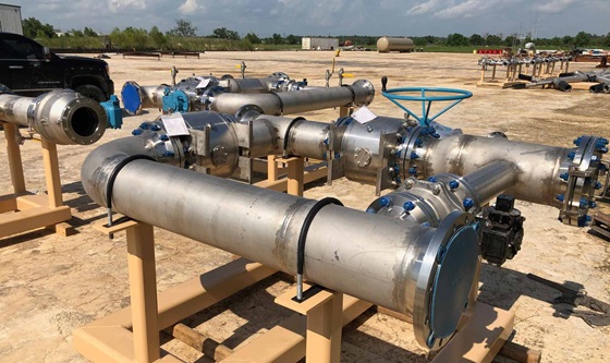
Spool splitting converts a continuous piping design into practical manufacturing and installation units. First, the designer identifies fixed equipment nozzles, tie-ins and field-weld locations. Next, the review considers lifting weight, transport envelope, access and erection sequence. Finally, the released documents assign each unit a traceable identity.
| Boundary factor | Why it matters | Information to define |
|---|---|---|
| Equipment interfaces | Fixed nozzles create critical locations where dimensions, flange alignment and allowable loads need control. | Nozzle orientation, face location, flange details, gasket allowance and installation tolerance |
| Field joints | Field welds or bolted joints allow crews to connect separately transported assemblies. | Joint type, end preparation, closure allowance, examination scope and field responsibility |
| Transport envelope | Road, container or site restrictions can limit overall length, width, height and weight. | Maximum shipping dimensions, lifting points, supports and permitted orientation |
| Installation access | Congested racks and structures may restrict rotation, lifting paths and tool access. | Erection direction, temporary clearances, sequence and removable obstructions |
| Testing strategy | Project test packs may group several fabricated piping spools within one system boundary. | Test limits, vents, drains, blinds, medium and reinstatement requirements |
| Coating and lining | Some systems require access for blasting, painting, lining or post-weld treatment. | Excluded areas, field-joint treatment, cure requirements and protection method |
Design responsibility: The owner or appointed piping designer should approve spool boundaries and field joints. A fabricator can review manufacturability, handling and inspection access against that controlled design.
Fabricated spools take their form from the piping layout rather than a fixed product catalogue. For example, one project may use simple straight sections, while another needs branched or offset assemblies around equipment and structures.
Prepared ends, couplings or flanges connect known interfaces. However, the drawing must still control length, facing, rating, bore and bolt-hole orientation.
Direction changes combine elbows and pipe lengths while preserving center-to-face dimensions and required orientation.
Similarly, concentric or eccentric reducers connect different line sizes according to the specified flow and drainage arrangement.
Tees, outlets or fabricated branches create additional connections and may introduce joint-specific reinforcement or examination requirements.
In addition, carefully controlled interfaces connect vessels, pumps, exchangers, skids and other fixed equipment.
Finally, detachable sections can provide access for maintenance, equipment removal, isolation or future modification.
For configuration-specific information, review our flanged pipe spool, elbow spool and removable spool piece pages.
Accurate fabrication starts with coordinated documents. Therefore, the production release should connect each spool drawing to the current isometric, piping class, bill of materials, line information and project specifications. A revision-control process must also prevent superseded information from reaching the workshop.
| Document or data | Typical content | Review purpose |
|---|---|---|
| Spool drawing | Spool number, geometry, cut lengths, fittings, welds, dimensions and orientation | Controls the individual fabrication unit |
| Piping isometric | Line routing, coordinates, flow direction, continuations and field joints | Confirms the spool within the complete line |
| Piping class | Materials, wall thickness, component ratings, branch rules and joining methods | Defines the approved component system |
| Bill of materials | Item descriptions, specifications, grades, sizes, quantities and remarks | Supports material issue and traceability |
| Welding documents | Approved WPS references, consumables, preheat, interpass and treatment requirements | Controls joint production |
| ITP or QAP | Inspection stages, hold points, examination extent and acceptance references | Coordinates verification and client involvement |
| Coating specification | Preparation, products, thickness, excluded areas, curing and repairs | Defines final surface protection |
See Pipe Spool Drawing for a detailed explanation of dimensions, weld references, component callouts and revision checks.
The approved project requirements determine the actual route. Nevertheless, most workflows connect document review, material control, joint production, inspection and release in a traceable sequence. The applicable code also depends on the project; for process-piping context, the official ASME B31.3 Process Piping page describes requirements for materials, fabrication, assembly, examination, inspection and testing within its scope.
First, the team verifies revisions, spool identity, materials, joints, dimensions and inspection requirements.
Next, identification and certificate checks connect issued pipe and components to the approved specification.
Controlled cutting and beveling establish the required lengths, end preparations and clean joint surfaces.
Meanwhile, fit-up checks control root gap, alignment, flange clocking, branches and drawing dimensions.
Qualified personnel follow the applicable WPS, consumable, parameter, preheat and interpass requirements.
In addition, the agreed plan may require visual, dimensional, NDT, hardness, PMI or pressure-test records.
Surface treatment, marking, tags and end protection prepare the spool for controlled handling.
Finally, document review, packing checks and release status complete the handover for delivery.
For coordinated production activities, visit pipe spool services and pipe spool assembly.
Inspection should follow the approved ITP or QAP rather than a generic checklist. First, material and drawing controls establish the correct basis. Next, fabrication-stage inspections verify joint preparation and fit-up. Finally, the release package records the examinations and dimensions required by the project.
Certificates, heat numbers and PMI when specified can link pipe and components to the approved materials.
In addition, weld maps can connect each joint to its WPS, welder identity, consumables and examination records.
Reports may cover overall length, center lines, branch locations, flange alignment and critical interfaces.
Similarly, the approved scope may specify visual, PT, MT, RT, UT or another suitable examination method.
When required, the procedure defines boundaries, pressure, medium, gauges, hold time, safety controls and drainage.
Finally, the dossier can organize drawings, material records, weld data, reports, treatment records and release notes.
Our Quality Control and Testing page explains the broader inspection workflow for pipe-spool projects.
Technical note: The design code, service category, material, joint type and client specification determine the required examination and acceptance criteria. Do not apply one inspection scope to every piping system.
A completed spool still needs a controlled path to its final position. Therefore, identification must remain legible, flange faces and prepared ends need protection, and supports must prevent handling damage. The packing plan should also respect coating, lining, cleanliness and orientation requirements.
In contrast, prefabrication describes the broader strategy of completing work away from the final installation location. The prefabricated pipe spools page covers scheduling, site-labor and installation-readiness considerations in more detail.
Fabricated spools are identified piping sections assembled from pipe, fittings, flanges, branches or attachments before site installation. A spool drawing defines each unit's geometry and interfaces.
The terms often overlap. However, this page explains spool definition, boundaries, documents and acceptance, while the fabricated pipe spools page focuses on Mesta Inc.'s commercial manufacturing offer.
The owner or appointed piping designer normally approves spool boundaries. Nevertheless, a fabricator can review manufacturability, field joints, handling, transport and inspection access.
Typically, the released package includes spool drawings or isometrics, a piping class, bill of materials, welding requirements, inspection plan and applicable surface-treatment specifications.
Yes. For example, projects may specify carbon, low-temperature, alloy, stainless or duplex materials. The approved piping class must define the exact pipe, fitting, flange and consumable combination.
Depending on the approved plan, inspections may include material verification, fit-up checks, visual examination, dimensional inspection, PT, MT, RT, UT, PMI, hardness or pressure testing.
Finally, projects normally use a unique spool number linked to the line, drawing and records. Approved tags, markings, orientation symbols and dispatch lists help crews place the correct unit.
Send Mesta Inc. the approved drawings, piping class, material requirements, quantities, inspection scope, surface specification and delivery schedule. Our team can review the manufacturing basis and identify the technical clarifications needed for quotation.