
Identification
Project, area, unit, line number, isometric number, spool number and revision connect the sheet with the correct piping system.
A spool piece is an identified, drawing-defined section of a piping system prepared for installation as one manageable assembly. This guide explains its components, dimensions, boundaries, fabrication stages and connection with project quality records.
A spool piece is a discrete section of an overall piping line. In addition, a fabrication team normally builds it from pipe and one or more approved components before site erection. Therefore, installers can handle, position and connect the section as an identified assembly instead of constructing the entire line from loose materials at the installation location.
For instance, the term can describe a straight piece or a more complex arrangement with elbows, tees, reducers, flanges, outlets or attachments. However, the approved piping isometric and spool drawing define the actual limits. Some spools end at flanges, while others end at field-weld points or another connection selected by the project.
This page explains the engineering concept. Buyers seeking specifications and quotations should visit Mesta Inc.'s pipe spool piece manufacturer page. Additionally, our prefabricated pipe spools page explains the wider off-site fabrication strategy.
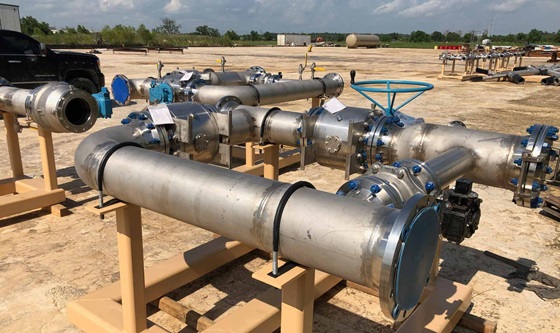
A spool piece may contain only pipe and end preparations, or it may combine several piping components. For example, the table below explains common elements and the information that controls them.
| Component | Function in the spool | Drawing or specification data |
|---|---|---|
| Straight pipe | Forms the pressure-containing barrel and establishes cut lengths. | Size, schedule or wall, material, length and end preparation |
| Elbow or bend | Changes direction and establishes centre-to-end geometry. | Angle, radius, material, wall and orientation |
| Tee or branch | Creates a connection to another piping route. | Run and branch sizes, type, reinforcement and orientation |
| Reducer | Transitions between different nominal pipe sizes. | Concentric or eccentric type, end sizes, orientation and length |
| Flange | Provides a bolted connection to another spool or equipment. | Standard, type, class, facing, bore, material and bolt-hole orientation |
| Outlet or coupling | Provides a branch, drain, vent or instrument interface when approved. | Type, size, rating, location and angular orientation |
| Attachment | Adds a support lug, trunnion, shoe, earthing boss or another specified item. | Detail drawing, material, weld type, location and examination |
| Field connection | Joins the spool to adjoining work during site erection. | Flanged, butt-weld, socket-weld, threaded or project-specific detail |
Moreover, a spool drawing converts the piping design into fabrication information for one identified assembly. First, it references the parent isometric and current revision. Next, it shows dimensions, components and weld locations. Finally, it provides the identifiers needed for fabrication, inspection and installation tracking.
Project, area, unit, line number, isometric number, spool number and revision connect the sheet with the correct piping system.
Centre-to-face, face-to-face, centre-to-end, cut lengths, elevations and coordinates control geometry.
Moreover, item numbers connect pipe, fittings, flanges and attachments with their specifications and quantities.
Weld numbers, joint types, shop or field designation and examination requirements support production control.
North arrows, elevations, branch angles and flange bolt-hole orientation clarify the spool's installed position.
In addition, notes may define slope, field allowance, cold spring, PWHT, coating or cleanliness requirements.
See the dedicated pipe spool drawing page for a deeper explanation of drawing fields and revision control.
Spool breakdown divides a complete piping route into sections that fabrication, transport and erection teams can manage. Consequently, designers consider geometry, weight, shipping envelope, lifting access, coating, heat treatment and installation sequence before placing spool breaks.
| Boundary | How connection occurs | Main planning consideration |
|---|---|---|
| Flanged boundary | Installers align gasketed flange faces and tighten specified bolting. | Facing protection, class, alignment, bolt access and gasket selection |
| Field-weld boundary | Site personnel complete the final welded joint between spool ends. | Fit-up allowance, weld access, examination and field conditions |
| Equipment interface | The spool connects to a pump, vessel, exchanger, skid or other nozzle. | Fixed dimensions, allowable nozzle loads, alignment and vendor data |
| Mechanical connection | An approved coupling, thread or proprietary joint connects sections. | Compatibility, restraint, sealing method and installation procedure |
| Field-fit piece | Site measurement establishes or confirms a final closure dimension. | Survey data, trim allowance, material control and approval workflow |
Important: A spool piece is not automatically removable during normal maintenance. A purpose-designed removable spool in piping needs suitable flanged interfaces, clearance, handling and an approved isolation arrangement.
A controlled fabrication sequence connects engineering information with the completed spool.
First, the approved isometric, spool drawing and material information establish the production basis.
Next, personnel identify components, review certificates, calculate cut lengths and prepare ends.
Then, fabricators position pipe and fittings while controlling alignment, orientation and joint preparation.
Qualified personnel complete specified joints under approved welding procedures and process controls.
Afterwards, inspectors complete required checks before approved surface treatment and preservation.
Finally, identification, connection protection and agreed records support dispatch to site.
Our fabricated pipe spools page covers the broader custom manufacturing service.
A spool number gives every assembly a trackable identity. For instance, project teams can use it to connect drawings, material records, weld maps, inspection status, coating records, packing lists and installation progress. This connection becomes especially important when one project contains hundreds or thousands of individual spools.
Heat numbers and material certificates can connect pressure-containing components with the spool record.
Likewise, weld numbers can link joints with WPS references, welder identity, NDT and repair history.
Inspection reports can record critical dimensions, flange alignment and branch orientation against acceptance criteria.
Moreover, spool registers can show fabrication, inspection, finishing, dispatch and site-installation progress.
Visit Quality Control and Testing for a focused guide to inspection methods and records.
Spool pieces appear in process piping, utilities, water systems, power plants, refineries, chemical facilities, equipment skids, marine systems and general industrial projects. However, the piping class and approved design always determine the material, configuration and acceptance requirements.
A straight run may use weld ends, flanges or another approved connection at its boundaries.
One or more flanges create bolted connections to piping, equipment or another spool.
Additionally, elbows create directional changes while the drawing controls radius, angle and orientation.
Tees, outlets and reducers create branches or size transitions within one identified assembly.
A purpose-designed detachable product provides planned access or separation under an approved arrangement.
In contrast, a dummy spool temporarily substitutes for another component during a defined project activity.
Before releasing a spool for fabrication, engineering and project teams should confirm the technical basis. Therefore, the release package should identify:
Additionally, teams should resolve clashes, fixed equipment interfaces and missing vendor information before final fabrication release.
A spool piece is an identified section of a piping system fabricated as one manageable assembly. It may include pipe, fittings, flanges, branches, attachments and prepared connection ends.
Projects normally use the term for a section prepared before final installation. However, the fabrication location and amount of shop work depend on the project execution plan.
A spool commonly carries a project-specific spool number linked with its line, isometric, drawing revision and installation location. In addition, marking may show orientation or match information.
A spool break marks the boundary between adjacent spool pieces or field-run piping. For example, it may occur at a flange, field weld, equipment nozzle or approved mechanical connection.
A fabrication team completes a shop weld before delivery under workshop conditions. In contrast, site personnel complete a field weld during erection between spools or field-run sections.
Not necessarily. A general spool piece forms one part of the permanent piping route. A removable spool needs purpose-designed connections, dismantling clearance, handling provisions and an approved maintenance or isolation function.
Depending on the order, records may include approved drawings, material certificates, weld maps, welding records, NDT reports, dimensional reports, test records, coating reports and release documents.
Send Mesta Inc. your approved drawings, piping class, spool list, materials, quantities, quality requirements and delivery schedule for technical review.