
Document Review
First, the team checks drawings, revisions, piping classes, bills of materials and project specifications.
Prefabricated pipe spools from Mesta Inc. are produced to approved drawings and project specifications. Moreover, controlled cutting, fit-up, welding, inspection, identification and delivery preparation help project teams shift planned fabrication away from congested installation areas.
A prefabricated pipe spool is a drawing-defined section of a piping system that a fabrication team assembles before site installation. For example, it can combine straight pipe, elbows, tees, reducers, flanges, branches, outlets and other approved components. In addition, the completed section carries a unique spool identity that connects it with drawings, inspection records and the installation plan.
Unlike loose piping materials, prefabricated piping spools arrive with much of the cutting, preparation, fit-up and welding already complete. Therefore, site crews can focus on lifting, alignment, bolted joints and planned field welds. The project still needs accurate drawings, controlled tolerances and practical transport dimensions to achieve that result.
Mesta Inc. produces custom spools for industrial project requirements. First, the team reviews approved information and clarifies the required scope. Then, production proceeds against the released documents. For detailed manufacturing activities, review our custom spool manufacturing capabilities. For coordinated service options, visit our project service overview.
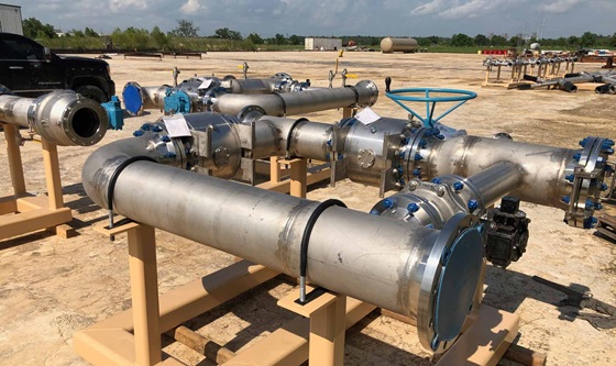
Each prefabricated pipe spool package follows its approved piping class, drawings and purchase-order requirements. Consequently, the following table acts as a procurement checklist rather than a fixed stock specification.
| Technical item | Typical project options | Information to specify |
|---|---|---|
| Design and fabrication basis | Approved isometrics, spool drawings, piping class, line list and bill of materials | Drawing numbers, revisions, governing construction code and client specifications |
| Pipe size and wall | Project-specific NPS/DN, schedule or stated wall thickness | Nominal size, outside diameter where needed, schedule, corrosion allowance and tolerances |
| Material | Carbon steel, stainless steel, alloy steel or another approved piping material | Complete pipe, fitting, flange, branch and filler-metal specifications |
| Components | Straight pipe, elbows, tees, reducers, flanges, outlets, couplings and approved attachments | Component standard, type, dimensions, quantity, rating and material grade |
| End connections | Butt-weld, flanged, socket-weld, threaded, plain or project-specific ends | End preparation, facing, flange class, bore, bolt-hole orientation and field-weld allowance |
| Welding | Qualified processes selected for material, thickness, position and service | Applicable code, WPS requirements, consumables, purging, preheat and interpass controls |
| Dimensional control | Overall dimensions, centre-to-face dimensions, flange alignment and branch orientation | Project tolerances, critical dimensions, hold points and survey-report requirements |
| Inspection and NDT | Visual and dimensional inspection; PT, MT, RT, UT or PMI when specified | Approved ITP/QAP, examination extent, acceptance criteria and third-party witness points |
| Pressure testing | Hydrostatic or pneumatic testing when the approved order requires it | Test procedure, medium, pressure, duration, safety controls and acceptance criteria |
| Heat treatment | PWHT or other controlled treatment where material, thickness or code requires it | Procedure, temperature cycle, recording method and hardness testing requirements |
| Surface condition | Clean, blast-prepared, painted, coated, pickled, passivated or preserved | Surface-preparation grade, coating system, DFT, color, exclusions and repair method |
| Identification and documents | Spool tags, match marks, weld maps, material records, inspection reports and packing lists | Marking method, document index, dossier format and final release requirements |
Technical note: The contract may specify construction standards such as ASME B31.3 Process Piping and component standards such as ASME B16.5 Pipe Flanges and Flanged Fittings. However, these references do not claim certification or replace the approved project documents, governing code or specified edition.
Prefabrication separates repeatable workshop work from site erection. As a result, teams can plan fabrication while civil, structural or equipment work continues at the project location. A controlled workspace also gives fabricators consistent access to tools, positioners and inspection areas.
| Project factor | Off-site prefabrication | Field fabrication |
|---|---|---|
| Work environment | First, workshop conditions support planned access, lighting and production flow. | However, weather, access restrictions and nearby activities can influence field work. |
| Schedule | Meanwhile, fabrication can progress in parallel with selected site activities. | In contrast, field production often depends more directly on site readiness. |
| Welding access | In addition, teams can position many joints for practical fit-up and welding. | Installed geometry may restrict access and welding position. |
| Inspection | Likewise, defined inspection stations can support repeatable dimensional and weld checks. | Inspection access depends on the installation area and surrounding work. |
| Material control | Moreover, spool-wise staging and identification can support traceability. | Material control must account for wider site storage and handling. |
| Main constraint | Finally, transport envelope, lifting, drawing accuracy and field-fit strategy require early planning. | Site labor, permits, access, weather and simultaneous operations require control. |
However, prefabrication does not remove all field work. Tie-in welds, final alignment, supports, equipment interfaces and site tolerances still need a coordinated erection plan.
A spool-wise workflow connects engineering release, production status and quality records. Therefore, each stage should follow the approved project documents and inspection plan.
First, the team checks drawings, revisions, piping classes, bills of materials and project specifications.
Next, personnel identify approved pipes and components and connect required certificates with the spool package.
Then, fabricators cut pipe, prepare ends and stage components according to released dimensions.
Meanwhile, fabricators control orientation, alignment and joint preparation before qualified welding proceeds.
Afterwards, inspectors complete specified checks while the team records status and applies approved finishing.
Finally, personnel verify spool identity, protect connection ends and prepare documents and delivery groups.
Approved routing and installation strategy determine the spool configuration. For example, a package may include straight runs, directional changes, branches, reducers or equipment connections.
One or more flanges provide bolted interfaces. Therefore, facing protection, class and bolt-hole orientation need clear control.
Elbows change piping direction. In addition, the drawing must define radius, roll angle, plane and tangent dimensions.
Meanwhile, tees, outlets or fabricated connections create branches while project requirements govern reinforcement and examination.
Similarly, concentric or eccentric reducers connect different pipe sizes and require the correct orientation for system service.
In addition, stainless materials may support corrosive or cleanliness-sensitive service when project specifications require them.
Finally, carbon or alloy steel options can serve general and project-defined temperature or pressure conditions.
Spool-break planning: Designers should consider transport dimensions, lifting weight, centre of gravity, erection access, support locations, equipment nozzles and planned field welds before releasing spool boundaries.
Quality control begins before cutting. First, project teams confirm document status and material identity. Next, stage inspections can verify preparation, fit-up, welding and dimensions. Finally, the release process connects accepted spools with agreed records.
First, heat numbers, material certificates and spool identification can link specified components with the finished assembly.
Next, WPS references, welder identity, weld maps and repair status help maintain a spool-wise welding record.
In addition, visual, dimensional, NDT, PMI and pressure-test reports document results according to the approved ITP.
Finally, a document index can organize drawings, certificates, weld records, reports, release notes and packing lists.
Explore our dedicated pipe spool quality control and testing page for the inspection workflow and common records.
Prefabricated pipe spools need clear identification, careful handling and practical installation planning. Therefore, each delivery should connect physical tags with the current approved production drawing, line number, inspection status and packing list.
Additionally, packing should protect flange faces, prepared weld ends, internal cleanliness and finished surfaces. Large or unusual assemblies may also need lifting points, transport supports or handling instructions. The approved delivery sequence can group spools by area, system, priority or erection order.
Projects that need a single replacement or connection section can also review our custom pipe spool piece page.
To request prefabricated pipe spools, send the latest approved technical package and explain the intended delivery sequence. Also include:
A prefabricated pipe spool is a drawing-defined piping section assembled before site installation. It typically combines pipe with fittings, flanges or branches and carries a spool number for identification.
Both terms can describe workshop-built piping sections. However, “prefabricated” emphasizes that work takes place before site erection, while “fabricated” often emphasizes the cutting, fit-up and welding operations.
A spool may include straight pipe, elbows, tees, reducers, flanges, outlets, couplings and approved attachments. Nevertheless, the released drawing and bill of materials define the actual configuration.
Include drawings, revisions, piping classes, materials, sizes, schedules, flange data, welding requirements, inspection scope, finishes, documentation and the required delivery sequence.
It moves planned cutting, fit-up, welding and inspection into a workshop before delivery. As a result, site crews can concentrate on receiving, lifting, alignment, bolting and defined field joints.
Yes, the order can include specified visual, dimensional and non-destructive examinations. Likewise, it may include hydrostatic or pneumatic testing when an approved procedure and agreed scope cover the activity.
Projects commonly use spool numbers, drawing references, line numbers and match marks. In addition, packing lists and spool registers can group items by system, area or erection sequence.
Send Mesta Inc. your approved drawings, spool list, material specifications, quality requirements and delivery schedule. Our team will review the package, identify technical clarifications and define the appropriate fabrication, inspection, documentation and dispatch scope.